Natural Period of a 3-Story Steel Frame — Modal Analysis Worked Example
A small three-story steel building analyzed for its natural periods, compared with the ASCE 7 approximate period, then changed in two ways: rotating some columns, and adding braces. The modal results explain why the first mode runs the "wrong" way, and how far an unbraced moment frame sits from the code's approximate period.
The building
| Framing | 2 × 2 bays at 25 ft, 3 stories at 12 ft (hn = 36 ft), steel moment frames in both directions, fixed bases, rigid floor diaphragms |
| Sections | Columns: I-shape d = 12, bf = 12, tf = 0.6, tw = 0.4 in (Iz = 510 in&sup4;, Iy = 173 in&sup4;) · Beams: d = 18, bf = 7.5, tf = 0.6, tw = 0.36 in |
| Mass | Member self-weight plus 1.0 kip/ft dead load on every beam: total 963 kip |
Model "3D building frame" with its defaults (2 × 2 bays, 3 stories), then open the Modes tab.
Open 3D frame analysis →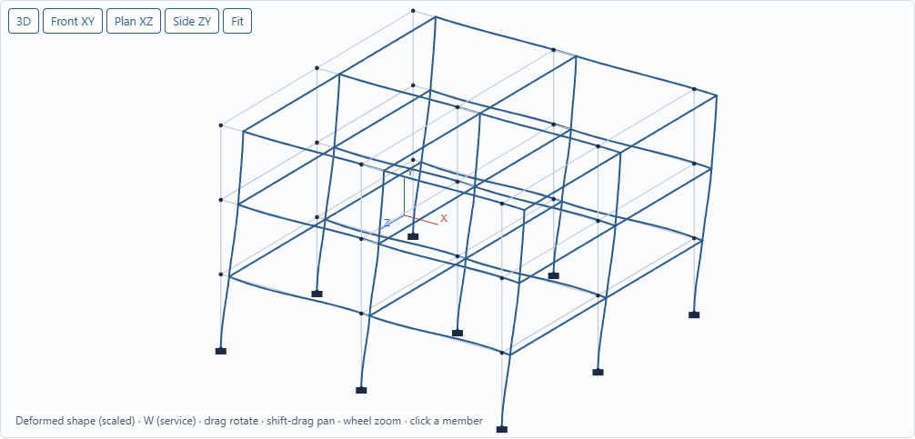
Six modes, periods and mass participation
| Mode | Period (s) | Mass X | Mass Z | Shape |
|---|---|---|---|---|
| 1 | 1.165 | 0% | 88.6% | 1st translation, Z |
| 2 | 0.896 | 0% | 0% | 1st torsion |
| 3 | 0.836 | 85.9% | 0% | 1st translation, X |
| 4 | 0.389 | 0% | 9.4% | 2nd translation, Z |
| 5 | 0.285 | 0% | 0% | 2nd torsion |
| 6 | 0.259 | 11.2% | 0% | 2nd translation, X |
Two modes per direction reach 98% of the mass in Z (88.6 + 9.4) and 97.1% in X, past the 90% that ASCE 7 §12.9.1.1 requires for a modal response spectrum analysis.
Every column has its weak axis facing Z
and the weak axis (Iy = 173 in&sup4;) resists Z sway: about one third of the stiffness from every column.
Turning the three columns on the middle frame line by β = 90° balances the building:
| Variant | T, Z mode (s) | T, X mode (s) | T, torsion (s) |
|---|---|---|---|
| All columns strong axis in X | 1.165 | 0.836 | 0.896 |
| Middle-line columns rotated 90° | 0.974 | 0.912 | 0.838 |
| X-braced end bays, both directions | 0.199 | 0.196 | 0.143 |
Ta = Ct hnx (ASCE 7-22 Eq. 12.8-8, Table 12.8-2)
Braced frame ("all other"): Ct = 0.02, x = 0.75 → Ta = 0.02 × 360.75 = 0.294 s; CuTa = 0.412 s
The analytical periods of the moment frame (0.84–1.17 s) are well above CuTa. For the equivalent lateral force base shear, the period used may not exceed CuTa = 0.689 s (§12.8.2). The code doesn't trust a bare-frame model to be that flexible, because nonstructural walls, stairs and slab action stiffen real buildings. Drift, on the other hand, is computed with the analytical model (§12.8.6.2).
Same braced building, diaphragms off
With the floor diaphragms turned off, the braced building's first period jumps from 0.199 s to 1.150 s, with only 37% mass participation. Braces exist only on the outer frame lines, so without a slab tying the floor together, the unbraced middle frame line sways on its own. A rigid-diaphragm constraint makes each floor move as one body in plan, which is how a concrete-on-deck floor behaves. If your floor isn't rigid (plywood, metal deck without fill), the truth lies in between.
Tools used in this example
3D frame analysis (3D building generator, rigid diaphragms, modal), and the frame modeling guide for local axes, β rotations and mass.
Frequently asked questions
What is the approximate fundamental period of a steel moment frame?
ASCE 7-22 Eq. 12.8-8 gives Ta = Ct·hn^x with Ct = 0.028 and x = 0.8 for steel moment-resisting frames (hn in feet). For a 36 ft building that is 0.49 s. The period used to compute the base shear may not exceed Cu·Ta, where Cu = 1.4 when SD1 ≥ 0.4.
Why does a frame model give a longer period than ASCE 7?
A bare-frame model ignores the stiffness of walls, stairs, slabs and connections that real buildings have, and the approximate formula is calibrated to measured buildings. That is why ASCE 7 caps the period used for base shear at Cu·Ta, while drift is computed with the model.
What does a rigid diaphragm do in a 3D frame model?
It ties all the joints of a floor together so the floor translates and rotates in plan as a rigid body, while each joint keeps its own vertical displacement. Lateral load then goes to the frames in proportion to their stiffness, and torsion is resisted by the frames' lever arms about the center of rigidity.