Fink Roof Truss — Member Forces and NDS Check, Worked Example
A standard residential roof truss, start to finish: turning roof pressures into panel-point loads, solving the member forces by the method of joints, and checking the 2x6 chords and 2x4 webs to the NDS with the right load-duration factor for each combination. Two results surprise most people: dead load alone governs the bottom chord, and the short 2x4 webs can use less than a quarter of their crushing strength because they buckle about the narrow face.
The truss
| Type | Fink (W), 28 ft span, 6/12 pitch, trusses at 24 in on center |
| Loads (horizontal projection) | TCLL 20 psf snow, TCDL 10 psf, BCDL 10 psf, BCLL 0 |
| Lumber | Douglas Fir-Larch No. 2: 2x6 top and bottom chords, 2x4 webs (NDS Supplement Table 4A: Fb 900, Ft 575, Fc 1350, Emin 580,000 psi) |
| Bracing | Top chord sheathed, bottom chord ceiling-braced, webs unbraced out of plane |
| Combinations (ASD) | D (CD = 0.9) and D + S (CD = 1.15) |
Every number below comes straight out of the free calculator with its default inputs.
Open the truss calculator →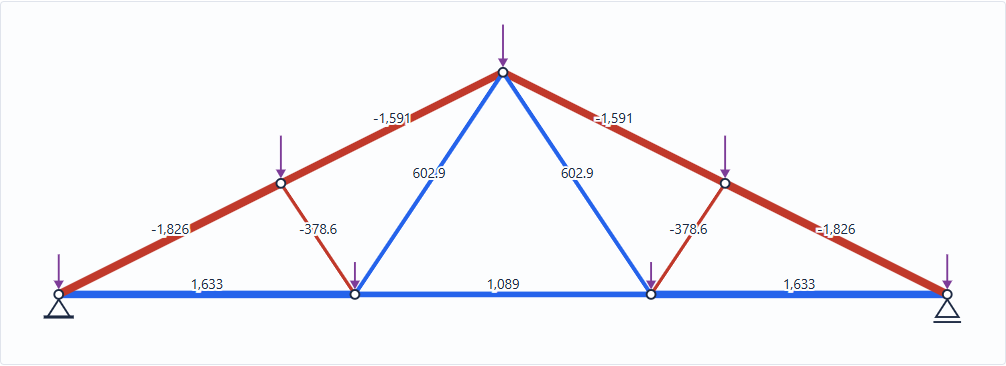
Rise, panel points and member lengths
Bottom chord joints at third points: x = 0, 9.333, 18.667, 28 ft
Top chord joints at quarter points: (7, 3.5), (14, 7.0), (21, 3.5) ft
Top chord panels = 7/cosθ = 7.826 ft Short webs 2–5, 3–7 = 4.206 ft Long webs 2–6, 3–6 = 8.413 ft
Tributary length × spacing × pressure
Bottom chord: 10 psf × 2 ft = 20 plf
Top joints 5, 6, 7 take 7 ft each → D 140 lb + S 280 lb = 420 lb
Heel joints take 3.5 ft of top chord + 4.667 ft of bottom chord → D 163.3 lb + S 140 lb
Bottom joints 2, 3 take 9.333 ft → D 186.7 lb
Total = 60 × 28 + 20 × 28 = 2,240 lb → R = 1,120 lb each end
The two biggest forces in the truss
ΣFy = 0: F1-5 sinθ = 816.7 → F1-5 = 816.7 / 0.4472 = 1,826 lb compression
ΣFx = 0: F1-2 = 1,826 × 0.8944 = 1,633 lb tension
Working inward joint by joint (or letting the calculator do it) gives the full set:
| Member | Joints | Size | D only (lb) | D + S (lb) | NDS ratio | Governs |
|---|---|---|---|---|---|---|
| Bottom chord, heel panels | 1–2, 3–4 | 2x6 | +793 | +1,633 | 0.454 | D + S, tension + bending |
| Bottom chord, center panel | 2–3 | 2x6 | +529 | +1,089 | 0.381 | D alone, tension + bending |
| Top chord, heel panels | 1–5, 7–4 | 2x6 | −887 | −1,826 | 0.473 | D + S, compression + bending |
| Top chord, apex panels | 5–6, 6–7 | 2x6 | −809 | −1,591 | 0.455 | D + S, compression + bending |
| Short webs | 2–5, 3–7 | 2x4 | −126 | −379 | 0.181 | D + S, compression (CP = 0.223) |
| Long webs | 2–6, 3–6 | 2x4 | +351 | +603 | 0.116 | D + S, tension |
Check: the reactions sum to 2,240 lb, and the truss is determinate (m + r = 11 + 3 = 14 = 2j).
NDS Eq. 3.9-3, member 1–5, D + S
Fc* = Fc CD CF = 1350 × 1.15 × 1.10 = 1,707.8 psi
In-plane le/d = 7.826 × 12 / 5.5 = 17.08 (sheathing braces the weak axis)
FcE = 0.822 Emin / (le/d)² = 0.822 × 580,000 / 17.08² = 1,635.1 psi
CP (Eq. 3.7-1, c = 0.8, α = 0.9575) = 0.6758 → Fc′ = 1,154.1 psi
Panel moment M = w·Δx²/8 = 60 × 7² / 8 = 367.5 lb-ft → fb = 4,410 / 7.5625 = 583.1 psi
Fb′ = Fb CD CF Cr = 900 × 1.15 × 1.3 × 1.15 = 1,547.3 psi
(fc/Fc′)² + fb / [Fb′(1 − fc/FcE)] = 0.0368 + 0.4359 = 0.473 ≤ 1.0 ✓
Member 2–3, tension + bending, NDS Eq. 3.9-1
D (CD 0.9): ft/Ft′ + fb/Fb′ = 64.1/672.8 + 345.6/1,210.9 = 0.381
D + S (CD 1.15): 132.0/859.6 + 345.6/1,547.3 = 0.377
Snow adds axial tension, but it doesn't add ceiling bending, and the higher load-duration factor raises every allowable stress by 28%. The permanent ceiling load at CD = 0.9 ends up slightly worse. This is why the NDS has you check each combination with its own CD, rather than only the heaviest load at the shortest duration.
Member 2–5, 2x4, 4.21 ft, compression 379 lb
FcE = 0.822 × 580,000 / 33.65² = 421.0 psi; Fc* = 1350 × 1.15 × 1.15 = 1,785.4 psi
CP = 0.223 → Fc′ = 398.1 psi; fc = 379 / 5.25 = 72.1 psi → 0.181
A 2x4 web carries less than a quarter of its crushing capacity because it buckles about the 1.5 in face. The 8.4 ft long webs are in tension under gravity, so slenderness doesn't hurt them, until wind uplift reverses them. See the wind-uplift example.
Pin-jointed elastic estimate
That is far inside L/240 and L/360. Real metal-plate-connected trusses deflect more, because of plate slip at the joints and creep under sustained load. Truss design software adds both. Treat the pin-jointed number as a lower bound.
Tools used in this example
Truss calculator (default inputs), with the truss member force coefficients card for a quick hand check. To put the truss on a girder or a header, carry the reactions into the continuous beam or beam deflection tool.
Frequently asked questions
What are the member forces in a 28 ft Fink truss?
For a 28 ft, 6/12 Fink truss at 24 in on center with 20 psf snow, 10 psf top chord dead and 10 psf bottom chord dead load, the heel top-chord panels carry 1,826 lb compression and the heel bottom-chord panels carry 1,633 lb tension. The short webs carry 379 lb compression and the long webs 603 lb tension. Each reaction is 1,120 lb.
Why is a roof truss top chord checked for bending?
The roof sheathing loads the top chord along its whole length, not just at the panel points, so each top-chord panel bends between joints while it carries axial compression. In a typical residential truss, the bending stress is several times the axial stress, and the NDS combined-stress equation, not the axial check, sizes the chord.
Which load duration factor applies to roof truss design?
Each load combination is checked with the C_D of its shortest-duration load: 0.9 for dead load alone, 1.15 for snow, 1.25 for roof live load and 1.6 for wind. Because a lower C_D can govern, dead load alone is always one of the checks.